BME_G02
 3 Delays (BNC Output)
- Delay-Resolution = 25ps
- 44 Bit Delayrange (max Delay = 429s)
- Edge or Gate Output
- Master/Slave Option if more than 3 Outputs are needed
- high Load Option
- external/internal Trigger
- external/internal Clock
 3 Delays (BNC Output)
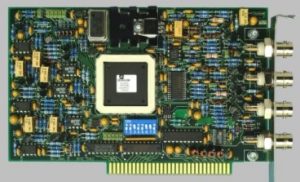
The BME_G02 is a PC-ISA card having 3 delay outputs that can produce delayed signals from 50nsec to 429sec, in steps of 25 picoseconds.
A trigger circuit starts the delay counters. There are 4 counters, T, A, B and an auxiliary counter. The T, A and B counters actually produce an output signal, while the auxiliary counter can only be used to produce an interrupt. In Edge-Mode the first level transition is determined by the programmed delay – after the last delay expired all outputs are reset together. In Gate-Mode the outputs A and B can be combined to form a gate signal, i.e. a rising(falling) edge after delay A has elapsed and a falling(rising) edge after delay B has elapsed, so you get an pulse with a variable(25ps resolution) pulse-width from 2ns to 429s.
The trigger can be produced internally by a modulo-N counter or by an external signal. The external trigger can by used as external clock, and can additionally can be gated and prescaled.
If more than 3 outputs (or more than 1 gate output) are needed, two or more cards can be connected together via a ribbon-cable, resulting in 6 or more synchronous delayed outputs.
General Specifications
| Delays | Delayrange | 50ns-429s (44bit) |
| Delayresolution | 25ps | |
| min. Delaytime | 50ns (Insertion-Delay) (32bit*100ns) | |
| Error | < (1ns +25ppm*delay)1 | |
| RMS Jitter
|
Output to Output: < (50ps + 10-8 * delay) 1
Trigger to Output: < (250ps + 10-8 * delay) )only BME_SG02 Trigger to Output: < (50ns + 10-8 * delay) ) BME_G03, BME_G05 |
|
| Trigger
|
External
|
Threshold Range: -2.5V to 2.5V in Steps of 1.2mV
Slope : rising or falling edge Input impedance : 10kR or 50R |
| Internal | by a modulo-N counter running with the main clock | |
| Outputs T0, A, B
|
Mode
|
50R or 25R
T0 output can be configured for NIM output pulse |
| Risetime | < 2ns for TTL < 1.2ns for ECL or NIM (typical) |
|
| Levels
|
TTL:0 to 4V normal or inverted
ECL: into -2.0 normal or inverted NIM |
|
| General
|
Clock Source
|
Internal: 10Mhz (80MHz) 25ppm 1
External: max. 250MHz with prescaler |
| Interface | PC ISA-bus I/O adressable between 000 and 3F0 H | |
| Interrupts
|
can be fired with the finish of any of the delays T, A, B or after the auxiliary delay has elapsed.
It is also possible to fire an interrupt with the main trigger of the delay generator(s), or after a fixed number of triggers has occurred. An Interrupt can be requested on lines int3 , int4,…. int7 of the PC XT/AT bus |
|
1 Accuracy and jitter depend on clock source (specs with 25ppm clock source) optional 1ppm clock source available
Options
| BME_SG02
|
Outputs synchronized to external trigger.
All other functions as for BME_G02 |
| BME_G03
|
Delays individually resettable with a resolution of 100nsec.
All other functions as for BME_G02 |
| BME_G04
|
Delays can be individually fired a second time after main trigger.
All other functions as for BME_G03 |
| BME_G05 | the outputs can be vetoed with a modulo-counter |